

Introduction: Replace Your Pool and Spa Controller With Raspberry Pi, Arduino, Node Red


In this Instructable I will describe how to build a pool and spa controller that controls a pump motor, multiple electric valve actuators, lights, a cleaner, air blower, and heater. It also measures the water and air temperatures. I built this to replace an old Compool pool controller which broke. The Compool model I had is obsolete and replacing it with a new controller and associated parts would cost around $800. I built this replacement for about $75 (using some parts I already had - buying all new will run about $100).
This pool controller uses Node Red on a Raspberry Pi to provide a web interface for controlling the various devices and displaying the temperatures. The Raspberry Pi has the high level logic to do things like determine whether to turn on the heater based on a temperature setting and the current water temperature and ensure that only valid combinations of devices can be operated at the same time. An Arduino Nano has the low level logic to turn on and off a set of relays which in turn control various motors and valves. The Arduino also reads the temperature sensors. The Raspberry Pi is inside my house and the Arduino is outside by the pool equipment; they communicate over a USB cable.
Rather than provide just a step by step listing of how I built this controller, I will also explain how the various controlled devices work. With that knowledge, you could easily build a controller for a brand new system rather than replace the controller for an existing system like mine.
This project requires some knowledge of electronics because you will assemble and solder various components together to build the controller. It will be helpful to understand the basics of reading a schematic because I provide two, one that describes the whole device and another that describes the power supplies. They are very helpful in understanding the controller as well as fixing any issues that might arise.
Let's get started!
Step 1: How Motors, Actuators and Heater Work


Each controlled device has its own method of operating. They require different voltages, some are AC and some are DC, etc. All of the devices connected to my controller fall into four categories: motors and lights, valve actuators, heater, thermistors.
Motors and Lights
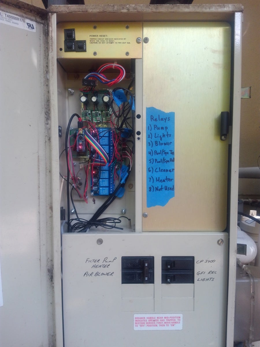
My system has a single 240V, 2HP electric motor. It is turned on by switching a heavy duty double pole relay which switches both lines of the 240V. The blower motor and lights operate on 120V electricity and use the same type of relay to operate (see picture). The relay is labeled "24VDC". I tested it and it requires only about 12-13VDC to activate and will stay activated until the applied voltage drops below about 3VDC. These are expensive relays, about $80 each, so I reused them. Feel free to substitute a different, cheaper brand if you are starting from scratch.
Valve Actuators
My pool has three valve actuators, i.e., electric motors that turn valves to make the water flow through different pipes. One is for the intake water - intake from pool or intake from spa. Another is for the return water - return to pool and spa or return to spa only. The third is for the automatic cleaner which operates with pressurized water diverted from the pump's output.
Valve actuators operate on 24VAC. They have three wires, typically black, red and white. Black is connected to the first leg of the 24VAC. To operate the actuator in one direction, you apply the second 24VAC leg to the red wire; to operate the actuator in the other direction, you apply the second 24VAC leg to the white wire. There are switches inside the actuator that stop it once it has reached its limit, i.e., you do not have to disconnect the power, you can just apply the power for the direction you want it to turn and leave it applied rather than having to somehow figure when it's gone far enough and cut the power. Also, the actuators have a three position switch (see picture of bottom of actuator). It turns the actuator off in the middle position, the other positions choose which direction it will turn - if you have it in one position, then applying power to red will operate it clockwise and applying power to white will operate it counterclockwise. If you have it in the other position, then applying power to red will operate it counterclockwise and applying power to white will operate it clockwise. This means that if you wire red and white backwards, all you have to do is flip this switch to the other direction to make it work properly. Sometimes you get lucky and mistakes don't matter!
Heater
My heater is a Hayward and it has a lot of complicated electronics inside as well as a ton of safety features that prevent it from running if water is not flowing, the temperature gets too hot, the gas supply falls below pressure and more. It sounds complicated, but the good news is that you don't have to worry about any of that. All it requires is two wires that either have 24VAC or 0VAC. It turns on when at 0VAC, off at 24VAC.
A heater will typically have two electrical connections, one for high voltage (120 or 240VAC) power and one for low voltage control power (24VAC). On my Hayward heater, both the low and high voltage could be connected on either the left or right side of the heater. There is a small panel on each side you can remove to get access to the connections. If you are replacing a controller, the high voltage line should not require any changes. The Hayward heater that I have can use either a two or three wire remote. A three wire remote just tells the heater whether to operate in pool or spa mode and the heater itself determines when to turn on and off based on its temperature settings for the pool and spa temperature (which are set on the heater's control panel). A two wire remote is basically just an on/off switch; whatever it is connected to determines when to turn the heater on or off. In this project, we are using the Raspberry Pi to check the temperature of the water and the pool and spa settings and turn on the heater if necessary, so we are using a two wire remote. This allows us to set the pool and spa temperature in the web interface rather than having to set those on the heater. The two connections used are the ones labeled POOL and 24V.
Thermistors
Thermistors are the devices that measure temperature. They are resistors whose resistance varies with temperature. Their resistance is about 10K. One of the thermistors I bought was made for pool use with a base and rubber O-ring so that it could be mounted in a hole drilled in a pipe carrying water to measure the water temperature. The other was a generic thermistor that I used for the air temperature; I bought a pack of five for less than ten dollars and that gave me extras to use for testing.
Step 2: Controller Design


I will describe how the controller works conceptually before we dive into how each of the pieces works.
A web interface has user controls to choose between everything off, pool or spa mode. It has switches to turn on the pool cleaner, lights, air blower for the spa, and to enable the heater. It has temperature gauges for the water and it allows you to set the temperature of the pool and spa so that when they are on, the heater will bring the water up to temperature and then turn off. It has a second temperature gauge for the outside air temperature.
The web interface is written in Node Red and runs on a Raspberry Pi which is inside my house. There is an Arduino Nano which is outside the house near the pool equipment. The Raspberry Pi monitors all the user controls and temperature settings and periodically communicates with the Arduino over a USB cable to tell it what to do with each of the various devices that the controller controls. The Arduino also measures the water and air temperature and sends that information back to the Raspberry Pi.
The Arduino controls the devices via a set of relays that switch various voltages either on and off, or from one connection to another to operate them. There are three small power supplies that provide three different DC voltages for various purposes.
The schematic shows the Arduino, relay board and power supplies. Even if you don't have much experience with schematics, It will be well worth your while to take some time to understand it - it does not have a lot of electronics mumbo-jumbo and is basically just a picture of how things fit together.
Step 3: Lexan Base

I used a piece of Lexan plastic as the base to mount all the circuitry for this controller. There were several different components (Arduino, relay board, etc.) and by mounting them all on one board, you can assemble it inside and mount it as a unit in the box outside next to the pool equipment. If you make sure every connection to something on that board is detachable, then you can remove it as needed to do repairs and upgrades.
I used 4-40 spacers, nuts and bolts to mount the various components to the Lexan and I used 8-32 machine screws to mount the Lexan base to the metal cabinet outside that used to house the old controller.
Step 4: Power


Above I mentioned that you need 24VAC for the heater and valve actuators as well as DC voltage of at least 12-13 volts for the heavy duty relays. My Compool controller had a transformer that provided 24VAC, 18VAC and 10VAC. I used the 24VAC directly for the valve actuators and heater. Later, you will see that in addition to DC power for the 24VDC relays, you also need 9VDC to power the Arduino and 5VDC to power the relay board. To create these three DC voltages, you need to build three little power supplies, all identical but set to the different voltages.
Take a look at the power supply circuit. It is a full wave bridge rectifier feeding into a smoothing capacitor which in turn feeds into a buck converter. The type I used is called the XM1584, it can handle input voltages up to 28VDC and will output up to 3A. See the attached pictures of a bare XM1584 next to a paper clip, which shows how tiny it is, and the completed circuit board with three power supplies. There is a small screw that you turn to set the output voltage. The output voltage must be less than the input voltage, so I set the three to 5VDC, 9VDC and 20VDC for the "24VDC" relays that actually require less than 24VDC to operate. The XM1584 buck converters are less than a dollar each from China and because they are switching power supplies, they do not get hot (unlike linear regulators). There are other models, e.g., LM2596, than would probably work just as well. I used a 1mF (1000 microfarad) electrolytic capacitor on the 5VDC and 9VDC power supplies and a 2.2mF capacitor for the 20VDC power supply.
I soldered all three power supplies on a single circuit board that is located near the top of unit because that is where the existing transformer leads are located. See the picture for the finished set of power supplies.
Step 5: The Relay Board

There are three motors and lights, three valve actuators and a heater. That is seven devices that need to be operated by routing power appropriately. This controller uses a relay board with eight relays. Each relay has one normally open contact and one normally closed. When looking at the relay, there is a little diagram that shows the center connection in contact with one of the other connections. That is the normally closed connection; the other is the normally open connection. The center pin will be connected to one or the other of the other two connections.
Each relay is operated by 5VDC which happens to be the output voltage of an Arduino pin. A nice feature of these boards is that the Arduino connections are isolated from the relay coil power, so there is essentially no possibility that voltage spikes from the relays will harm the Arduino. In order to take advantage of that, use a 5VDC power supply that is not connected to the Arduino (this is the purpose of the 5VDC power supply described in the prior step).
There are two headers on the relay board, a ten pin header and a three pin header. The three pin header is for the relay coil power (i.e., the 5VDC mentioned above). Make sure to remove the jumper and connect positive to the JD-VCC pin and negative to the GND pin. The ten pin header controls the relays. Connect the VCC connection to the 5V pin on the Arduino and the GND connection to the GND pin on the Arduino that is next to pin D2. The other eight pins control the eight relays. The relay is off when the pin is high (5V) and the relay is on when the pin is low (0V).
In order to connect the actuators, heater and other relays to the relay board, I salvaged the various connectors from the old controller board and soldered them to a small circuit board which I then connected to the relays on the relay board.
The first three relays on the relay board are used to turn on the heavy duty relays for the pump, lights and blower respectively. Each of those requires 20VDC, so wire the positive connection of the 20VDC power supply to the center connection and run a wire from the normally open connection to either wire of the heavy duty relay. Connect the negative connection of the 20VDC power supply to the other connection of the heavy duty relay.
The next three relays on the relay board are used to make the actuators go in one direction or another. Connect one leg of 24VAC to the black wire of each actuator. Connect the other leg of 24VAC to the center connection of the three relays. Connect the normally closed connection of the relay to the red wire of the actuator and connect the normally open connection of the relay to the white wire of the actuator (remember, it's not critical, but just being systematic here).
The seventh relay is used for the heater. The heater requires 24VAC to be off and 0VAC to be on. Connect the first leg of 24VAC to one wire of the heater and to the normally open connection of the relay. Connect the second leg of the 24VAC to the normally closed connection of the relay. Connect the second wire of the heater to the center connection of the relay. This means the when the relay is off, one wire of the heater is connected to the first leg of the 24VAc and the other wire is connected to the second leg of the 24VAC, so the heater gets 24VAC. When the relay is on, both wires of the heater are connected to the first leg of the 24VAC, so the heater sees a 0VAC potential difference and turns on.
Step 6: Arduino and Thermistors
Solder an IC socket to a small circuit board so you can easily remove the Arduino for programming. Solder headers to the circuit board and connect them to the pins of the IC socket so you can use jumper wires to make connections to the relay board and other places. Use a ribbon cable with header connectors on the ends to connect the Arduino to the relay board. Connect pin D11 on the Arduino to relay IN1, pin D10 to relay IN2, etc.
Get or make two wires that have a female header connector at one end and bare wires on the other end. Solder them to the positive and negative connections of the 9VDC power supply and connect the header connectors to the Arduino VIN and GND pins.
Create the voltage dividers with the thermistors. Connect 5VDC from the Arduino to one end of a resistor. Connect GND from the Arduino to one wire of the thermistor. You now have one unattached wire of the thermistor and one unattached end of the resistor. Connect these together along with a connection to an analog pin on the Arduino (pin A0 for the water temperature thermistor and pin A1 for the air temperature thermistor). As you can see in the picture of the full controller, I used a separate circuit board for the thermistor connectors, but if you can fit them on the same circuit board as the Arduino, that would be better.
The Arduino communicates with the Raspberry over a serial connection, i.e., a USB cable plugged into the USB connector. The Arduino writes the values of the water and air temperature to the serial port and it reads the desired state of the relays from the serial port. The attached sketch implements that. Setting the relay pins is just a digitalWrite() function call, while reading the temperature involves reading the raw voltage and then applying a standard formula (which you can find on Wikipedia) to convert that to degrees Fahrenheit (simple change to make it Celsius).
If you have never programmed an Arduino before, It is not difficult. There are many sources that describe how to do it, like this Instructables class. Upload the attached sketch to your Arduino. Then plug it into the IC socket on the circuit board - make sure the pins are lined up properly!
The Arduino has to do two things: respond to commands from the Raspberry Pi to set the relays, and read the water and air temperatures and send them to the Raspberry Pi. It uses serial communication for this.
When a serial message is received on the serial port, the function serialEvent() is called. The format of the relay setting is a single byte where each of the eight bits in the byte corresponds to one of the eight relays. Having the entire message in one byte means there is no need to worry about where the message starts and ends - every byte is a complete message. The byte is decomposed and the bits used to set the relays. It does this every time for all bits, even if the state of the bit has not changed. This is very simple and reliable; there is very little logic in the Arduino code which minimizes the chances of a bug in that code.
The main loop() function of the Arduino calls the function getTemp() twice - once to get the water temperature and once to get the air temperature. The function itself implements a formula you can find on Wikipedia or other places which converts the resistance of the thermistor to a temperature. The temperatures are sent in strings to the Raspberry Pi. Future upgrades (the subject of a future Instructable!) will likely require more than one byte of data, so in this case a string is used with a keyword for the type of data followed by the data itself. The loop has a delay of 2 seconds (2000 milliseconds) because there is no need to send the temperature any more frequently.
That's all the Arduino has to do, set relays and read temperatures. The Raspberry Pi handles everything else.
Attachments

Step 7: Raspberry Pi and Node Red

The pool controller logic is implemented in Node Red on a Raspberry Pi. Node Red is a system that allows you to create logic flows graphically. The graphical representation makes it easy to understand the flow. You have to do a bit of programming in the nodes but that is not hard.
The UI is implemented with a set of Node Red nodes called the Node Red Dashboard. These nodes provide the dropdown that lets you choose pool, spa or off, the switches to turn on the cleaner, blower, lights and heater, the gauges to show water and air temperature, and the numeric input that lets you set the pool and spa temperatures. It automatically formats the various controls so it looks nice and works properly on a desktop computer web browser or on a smartphone browser.
The model for this flow is that inputs that come in via the serial port from the Arduino and from the various Node Red Dashboard controls set the state of the system. Periodically, a separate process reads the current state of the system, figures out what needs to be set on the Arduino and sends the appropriate commands as a serial message to the Arduino.
For example, there is a switch in the UI called Cleaner. When that switch is turned on, it sets a variable called CleanerSetting to true. There is a node called PoolControlHearbeat that reads the value of CleanerSetting. If it is true, it sends a message to the Arduino to turn on the relay for the cleaner.
If you have not used a Raspberry Pi before, there are many sources that describe how to get one up and running, like this Instructables class. You need to install Raspbian with the desktop so that you can perform the following steps and you will need to connect it to a monitor, keyboard and mouse to set this up, but after it is all set up you will not need the monitor, keyboard or mouse. You probably also want to set it to have a static IP so that you can access it from other devices in your home easily, and if you are going to run it headless, i.e., without monitor, keyboard or mouse, then you will need to enable ssh access (select Raspberry Pi config from the main menu to find these options) so you can access it if you ever need to power it down cleanly (it's not a good idea to just pull the power plug on a Raspberry Pi). For security reasons, I set mine up so that it is only accessible from my home intranet (not from the outside internet). Also, use Raspberry Pi config to ensure logins over the serial port are disabled (for two reasons: you will be using it to communicate with the Arduino so you do not want it to be sending login prompts to the serial port, and so that someone cannot unplug the USB cable and login to it from outside your house).
Lastly, install the Chromium browser and use that for Node Red; as of this writing, Chromium works best with Node Red. After you have set everything up and are logged in, check the main menu - Node Red should be an option on the Programming menu. Select that and let it start to make sure it works. You will need to perform a step to make Node Red start when the Raspberry Pi is booted (so you will not need to start it from the menu every time you restart the Raspberry Pi). Execute the following command in a Terminal window:
sudo systemctl enable node-red.service
Then, reboot. (Note: you need to start it as a service before you import the flow below, otherwise it will not find the flow you imported, so enable it as a service as just described before continuing.) Open the Chromium browser and connect to the address http://localhost:1880. That will open the Node Red workspace in your browser. Check if Node Red Dashboard is installed because it might not be installed by default. Open the menu (hamburger icon at the upper right), then select Manage Palette. Under Nodes, search for node-red-dashboard. If it is not there, go to Install, search for and install it. Once it is installed, you will see a set of nodes under the category dashboard with names like button, switch, gauge, chart.
You can now import the entire flow shown graphically in the attached picture by importing the file attached to this Instructable is called PoolControlFlow.txt. Download it and put it on a USB drive that you insert into your Raspberry Pi. Go to the Node Red menu on the browser page and choose Import. Navigate to the PoolControlFlow.txt file and select it. That will import the entire flow that runs this pool controller, so you don't have to program it all yourself.
Test that you can access the UI is accessible from the browser, too. Open the URL http://localhost:1880/ui. If you set a static IP, try accessing the UI from another computer or smartphone by substituting the IP address for the word localhost in the URL. If you have an Arduino on a breadboard for testing as described earlier, then you can connect it with a USB cable and try the various controls to see the LEDs go on and off (note that and LED on corresponds to the relay being off, and vice versa - that's how the relay board works). You can also connect a couple of spare thermistors for testing that the temperature gauges work.
Node Red Flow Description
If all is working, then you don't need to read this section, but if you are interested, this explains how the various parts of the Node Red flow work.
The ArduinoSerialGet node listens on the serial port for messages from the Arduino. Those messages have a keyword, one of H2O or AIR, followed by a colon and a number that is the value. The SerialMsgRouter node routes the message to one of two nodes corresponding to the keyword. The string is converted to a value that is sent to a gauge on the UI and a node that sets the value of a variable, H2OTemp or AIRTemp.
There are two nodes that set the default temperature settings for the pool, DefaultPoolTemperature (set in the node to 82) and DefaultSpaTemperature (set in the node to 100). Those values feed into the numeric controls on the UI so they have an initial value and also into the PoolTempSetter and the SpaTempSetter which set variables with the values. These are like thermostat settings, they are the temperature you want the pool water to be, while the H2OTemp is the temperature that the pool water is. The RelaySetter (described below) uses these to decide when to turn on the heater.
The Light switch turns the lights in the pool and spa on or off. The can be turned on whether the pool or spa is running or not.
The HeaterEnable switch does not directly turn on the heater. If it is off, then heater will not turn on in any situation. If it is on, then the heater will turn on if needed (see below). This allows you to maintain your temperature settings but not heat the pool until you decide to enable the heater.
The Cleaner switch turns on the automatic cleaner which is driven by a water line from the pump. That is controlled by a valve actuator.
The Blower switch turns on the air blower which adds bubbles to the spa. The blower is an electric motor.
The dropdown Off/Pool/Spa can be set to one of three values: Off, Pool or Spa. This sets a variable, PoolSpaMode to one of those values. This mode is also part of what is used in the RelaySetter to determine when to turn on the heater. The mode also enables or disables certain controls. If the pool is on, then you do not want the air blower for the spa to be turned on. Conversely, if the spa is on, then you do not want the cleaner to be turned on. So, whenever the pool is turned on, it turns off the blower switch and disables it, and also enables the cleaner switch. Whenever the spa is turned on, it turns off the cleaner and disables it, and also enables the air blower. Whenever the Off setting is chosen, it turns off both the cleaner and blower.
The PoolControlHeartbeat periodically sends a message to the RelaySetter which triggers it to check the settings of the cleaner, blower, lights and send the corresponding relay settings to the Arduino. The RelaySetter turns on the pump relay if the mode is Pool or Spa and turns it off if the mode is Off. The RelaySetter also turns on the heater if necessary. It does this by first checking to see if the HeaterSetting is on, i.e., if the heater is enabled. If the heater is enabled, then it determines what is the appropriate temperature setting - if the mode is Pool, then it uses the PoolTempSetting value; if the mode is Spa, then it uses the SpaTempSetting value. It compares that value to the H2OTemp value, i.e., the current water temperature. If the current water temperature is below the setting, then it turns on the relay for the heater, otherwise it turns it off. Lastly, the RelaySetter sets the intake and return valve actuator relays to off if the mode is Pool and on if the mode is Spa.
Once all relay values are known, a single byte is created where each bit corresponds to a relay and where the bit is set (value 1) to turn on the relay and the bit is unset (value 0) to turn off the relay. This byte is sent as a serial message to the Arduino by the ArduinoSerialSet node.
Attachments
Step 8: Put All the Pieces Together


At this point, you have power supplies, a relay board, a curcuit board with a socket for the Arduino and the thermistors, and a circuit board with sockets for the devices controlled by the relays. Now you need to put all those pieces together. The pictures show two views without some of the cables so you can see how I laid out the components and another with the cables so you can see how it looks completely assembled. Refer to the schematic in the Controller Design section as well.
Drill holes on the Lexan backer to mount the relay board and other circuit boards. Use 4-40 spacers to mount the boards.
The positive output from the 24VDC power supply goes to the middle terminal of each of the relays #1, 2, 3. Daisy chain the connections, i.e., use one wire from the 24VDC power supply to the first relay, then a short piece of wire from the first relay to the second, and again to the third. The normally open (NO) terminals of those relays go to the corresponding connector for the heavy duty relays. The negative output from the 24VDC power supply goes to the second connection for each of the heavy duty relays. There is no connection to the normally closed (NC) terminals of the first three relays.
The positive output from the 9VDC power supply goes to the VIN pin of the Arduino and the negative output from the 9VDC power supply goes to the GND pin of the Arduino. The easiest way to make the wires you need is to get two jumpers with a female header connector on one end and cut off whatever is on the other end and strip the wire.
The 5VDC power supply must only be used for relay board power to achieve the isolation of the inputs from the switched relay connections. Remove the jumper on the three pin header. Connect the positive output to the JD-VCC pin and the negative output to the GND pin.
Connect leg one of 24VAC to the middle terminal of relays #4, 5, 6. Connect the NC terminal to the red wire of each valve actuator and the NO terminal to the white wire of each valve actuator. Connect leg two of 24VAC to the black wire of each valve actuator.
Connect leg one of 24VAC to the NC terminal of relay #7. Connect leg two of 24VAC to the NO terminal of the relay and one side of the heater connection. Connect the middle terminal of relay #7 to the other side of the heater connection. This ensures it is never floating, it is at 24VAC when the relay is off and at 0VAC when the relay is on.
Jumper wires often come in strips of multiple wires fastened together. If you have some like this, peel off a set of ten. Connect one end to the ten pin header on the relay board. Connect the other end of the GND wire to the Arduino Nano GND at the pin next to the RST pin. The other end of the VCC wire has to be connected to the 5V pin on the Arduino, but that is also required for the thermistors, so solder to the same board as the thermistors or add a header pin to that board and plug in the jumper.
Connect the first seven relay inputs to pins D11 through D5 on the Arduino (relay #8 is not used, so I deliberately left it unconnected so it cannot activate the relay).
I salvaged a number of two and three pin PCB headers and corresponding plugs from the old controller by desoldering them. You can do that or buy similar connectors and a crimping tool to make your own. Or, you can buy terminal blocks that you can solder to the circuit boards so all you have to do is strip the wires to be connected. The key thing is that while it is fine to solder connections between circuit boards on the Lexan backer, you want everything that connects something external to the Lexan backer to be a plug and socket so you can easily remove the Lexan backer with all of the circuit boards, relay board and power supplies and work on it in a more convenient location if necessary. I made a couple of mistakes where I had to rewire and resolder certain parts and it was easy since I could just remove the whole panel and bring it to where I had the solder iron and other tools. Label the various plugs and sockets to make it easier to reconnect everything. Put all the two and three pin headers on a separate circuit board next to the outputs of the relays since that is where they all need to be connected.
Add a power connector for the power supply input. I also salvaged that from the old controller so that it would fit the plug that was already fitted to the transformer output.
Step 9: Optional: Test Setup


It is handy to test the controller without having to connect it to the actual pool equipment. You can do this with a breadboard, two spare thermistors, two 10K resistors, seven LEDs, seven 100 or 220 ohm resistors and some jumpers. Create a voltage divider just like the main unit with the thermistors and and 10K resistors and connect the midpoint to pins A0 and A1. Connect each of the pins D5-D11 to one end of a 100 or 220 ohm resistor, then connect the other end of the resistor to the positive lead of the LED, then connect the negative lead of the LED to the ground bus. Connect the power and ground buses to the 5V and GND pins of the Arduino. Connect the USB connector to the Raspberry Pi and boot up the Raspberry Pi. It will power the Arduino via the USB cable.
In the Off setting of the interface, all of the LEDs should light (counterintuitive, yes, but recall that the relays are off when their inputs are high and on when low). As you try the different settings of pool, spa, blower, cleaner and heater, the LEDs should turn on and off appropriately.
The Node Red interface should show the air and water temperatures which you can test by dunking in hot or cold water.
You can test the heater by setting the pool or spa temperature above and below the water temperature shown on the gauge and watching the heater relay LED (pin D5) turn on when the settting is below the water temperature and turn off when the setting is above the water temperature.
Step 10: Install
Now that you have completed the controller unit, you need to mount it by your pool.
Note: the voltages involved with pools include 24VAC, 120VAC and 240VAC, easily enough to kill you if you touch the wrong wires or wire something incorrectly. If you are not experienced with electrical work like this, get an expert to set that up and do just the low voltage part yourself.
Drill holes for 8-32 machine screws in the enclosure that has the power and transformers supplying AC and mount the Lexan to it. Or, if not replacing a unit like I was, create an enclosure with appropriate power supplies. (If you are starting from scratch, you don't have to have three different AC inputs, you can pick whatever is available and cheap for the transformer, as long as it can supply 24VAC and the three DC power supplies.)
Run a USB cable from the enclosure at the pool into your house for the Arduino to Raspberry Pi connection. If you are replacing a controller, there will already be a cable routed between the two locations. Attach the USB cable to that and pull it through. NB: You might ask why not just put the Raspberry Pi outside the house in the pool enclosure as well? That would certainly work and avoid running cables into your house, but keep in mind that the Raspberry Pi has a direct connection to your home network via wifi, including the wifi password, so if it is outside, anyone can get to it and gain physical access to your home network.
The water temperature thermistor needs to be mounted in the water pipe. My old controller's thermistor was mounted in the PVC pipe just downstream of the pump. The new thermistor was slightly larger, so I had to drill the hole out a bit. Run the wire into the enclosure and put the appropriate connector on the end for attachment to the connector on the circuit board. The generic thermistors I bought already had a two pin connector, so it fit into a two pin connector that I salvaged. Place the generic thermistor inside the enclosure with the controller board, that will be the air temperature it measures.
Mount the Raspberry Pi somehow and run power to it. I initially intended to run 5VDC from the controller to the Raspberry Pi so that I would not need a separate power cord, but after reading more about it, decided it was better to power it the normal way, i.e., with a 5VDC power supply inside the house connected to the micro USB connector.
Connect all the controlled devices first, then the USB cable to the Raspberry Pi, then connect power to the unit and turn on the circuit breaker. Nothing should happen except a light glowing on the Arduino since the default is for everything to be off. Start the Raspberry Pi (which should automatically start Node Red if you followed the earlier instructions). Bring up the interface on a web browser and turn on the pool. Check the water and air temperature gauges to make sure they make sense. Test all the other functions to ensure they work. Check that the valve actuators turn in the proper direction; if not, just set the switch on the actuator to its opposite setting.
After you test that all is working, you can run the Raspberry Pi in headless mode. Power it down, disconnect the display and keyboard, then power it back up and test you can still access the web interface and can ssh to the Raspberry Pi.
You're done! Enjoy your pool and spa!
Step 11: Troubleshooting
Note: the voltages involved with pools include 24VAC, 120VAC and 240VAC, easily enough to kill you if you touch the wrong wires or wire something incorrectly. Many of the steps below require the main power to be on so that you can check for proper voltage at the controlled devices. If you are not experienced with electrical work like this, get an expert to help with the troubleshooting.
The relay board has a red LED for each relay that turns on when the relay is activated. If some device is supposed to be on, check that the red LED is on. If the LED for the wrong relay is lit, then check that the jumpers are wired correctly from the pins D5-D11 onthe Arduino to IN1-IN8 on the relay board. If the proper red LED is lit, use a multimeter to determine where in the chain from power supply to the device it is failing. If there is the appropriate voltage at the device, then check the device itself.
The thermistors should have 5VDC applied between the end of the resistor that is connected to the 5VDC connection on the Arduino and the wire of the thermistor that is connected to GND. Check that first, then if it is okay, check that the voltage at the three way connection (other end of the resistor, other wire of the thermistor, wire to pin A0 or A1 of the Arduino) is at some voltage roughly midway between 0 and 5VDC. Make sure the jumper is connected properly to pin A0 or A1.
If the problem is on the Raspberry Pi end, power it down over ssh and restart with a display and keyboard attached. Open Node Red in a browser. The serial interface nodes should show that it is connected to the Arduino. You can add a Debug node to the same output that sends the serial message to the Arduino so that you can see the value of the serial bytes in the Debug window in Node Red. You can add Debug nodes anywhere else to check what is happening. Remember to redeploy after adding or changing any nodes.
The service and installation manuals for heaters, valve actuators, pumps, etc. are often available online. If your device is not like the ones described here, it might be well worth your while to find the manual and see what it says about how it works and how to use it. For example, the manual for my Hayward heater describes in detail the electrical connections and the difference between two and three wire remotes (though it didn't mention that 0VAC is on and 24VAC is off; that I discovered by trial and error!).
Step 12: Parts List
This is a list of the parts used. Prices are for buying from US sources like Amazon. You can save a fair amount by buying electronics from China, e.g., from AliExpress, if you are willing to wait a little for the shipping. Buy things like Arduinos and buck converters and protoboard in multiples of three or five or ten, then you'll have some extra for future projects!
Raspberry Pi - about $35 plus power supply, case - I used a model 3 which has built in wifi but any model that can run Node Red and can connect to your home network. I'm planning to try a Pi Zero W ($10).
Arduino Nano - about $8 for one from local sources or $3 each in multiples of 5-10 from AliExpress or other similar sites - other models would also work but you might have to change the sketch to accommodate different pin layouts. You need one with at least seven digital outputs (for the relays) and two analog inputs (for the thermistors).
Lexan - about $5 for an 8.5x11 sheet from Lowe's or Home Depot
Water thermistor - about $25 - Pentair 520272 from Amazon
Air thermistor - about $2 each in a pack of 5 - OCR 10K-5
USB cable to connect Raspberry Pi and Arduino Nano - about $8 - $10 depending on the length - Cable Matters Gold Plated Hi-Speed USB 2.0 Type A to Mini-B Cable
Relay board - about $7 each in a pack of two - Huayao 2pcs 8 Channel DC 5V Relay Module with Optocoupler for Arduino
Buck converter - about $1.20 each in a pack of 10 (you need 3 for this project) - LIGHTHINKING 10PCS XM1584
Circuit boards (a.k.a., protoboard) - about $6 each, get two - Busboard Protot SB400
Capacitors: 1000uF or 2200uF (not critical) - about $6 for a pack of 10 - Nichicon 2200uF, Nichicon 1000uF. You can use 1000uF or 2200uF for all three, I just happened to have two 1000uF and one 2200uF.
Resistors: 10K ohm - $4 for 100 - 100 Uxcell 10K resistors
Wire and solder
Jumpers
Screws and spacers for circuit board mounting
Optional: breadboard, resistors and LEDs for the test setup
Tools: soldering iron, multimeter, drill
Total cost for parts is about $100 including extras as mentioned above. If you are like me and already have Arduino Nanos, capacitors, buck converters and other items sitting around waiting to be used in projects like this, it will cost less. A lot of electronic parts, like resistors and capactors, are much cheaper if you buy them in assortments that include a number of different sizes and several of each size.
Step 13: Update: Schedule Mode and Pi Zero W
Since I wrote the original Instructable, I made a few changes to NodeRed flow. I added a schedule mode so I can set a schedule for when the pool, spa and cleaner are on. I also added a freeze mode which monitors the air temperature and turns on the pool if the temperature falls below 37 degrees Fahrenheit. This updated flow is attached as PoolControlFlowWithSchedule.txt. Import it into NodeRed and modify the times to suit your needs.
All of the times are grouped together at the top of the flow so that you shouldn't have to dig to deep into the code just to get it to work. The times are in 24 hour format, so [ 8, 0 ] means 08:00 in the morning, [ 21, 30 ] means 9:30 in the evening (21:30), and 15 minutes after midnight is [ 0, 15 ]. You can set the pool schedule, spa schedule and cleaner schedule. The schedule controls the pump and the various actuator valves. It's essentially doing the same thing in code as someone selecting Pool, Spa and Cleaner Enable from the Dashboard, but does it in code. For example, suppose you have the following schedule.
const spaSchedule = {
    start: [ 8, 0 ],
    end: [ 8, 15 ]
};
const poolSchedule = {
start: [ 8, 15 ],
end: [ 20, 0 ]
};const cleanerSchedule = {
start: [ 8, 20 ],
end: [ 11, 30 ]
};This starts the pump and sets the actuator valves to spa mode at 08:00, then at 08:15 switches the actuator valves to pool mode, then at 08:20 it turns on the cleaner. At 11:30, it turns off the cleaner, then at 20:00 (8:00 in the evening), it turns off everything.
Once you've set the times and imported the flow, the dropdown that formerly provided the options Off/Pool/Spa will have the options Off/Pool/Spa/Schedule. Select Schedule to run the schedule you set or choose Pool or Spa to override the schedule and run the pool or spa as you wish.
The freeze mode runs the pool and spa alternately for 15 minutes at a time. It accomplishes this by simply checking the current time and calculating which quarter of the hour it is in. The code runs one for the first 15 minutes of the hour, the other for the next 15 minutes, etc.
Usually, just ensuring the water is flowing will keep it from freezing. If it is cold enough, however, the water could still freeze (this happened once in 14 winters at my home, during the winter prior to this project). To prevent that, you can enable the heater on the Dashboard and set the pool and spa temperatures to some value just above freezing, e.g., 34 degrees so that it will turn on before the water actually freezes. This will work in Schedule mode. Of course, it will only work if you have not winterized the heater and thus disabled it!
Another update was using a Raspberry Pi Zero W which is cheaper than a full Raspberry Pi 3 ($10 vs. $35). I simply replaced the Pi 3 with the Pi Zero W and inserted the same MicroSD card. The card is interchangeable between the devices, so I find it convenient when making changes to shut down the Pi Zero W, transfer the card to a Pi 3, make the changes, transfer the card back to the Pi Zero W and boot. It works great!
Attachments

Runner Up in the
Fix It! Contest


